
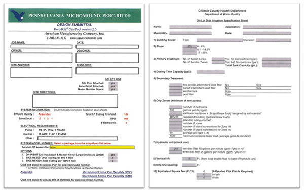
The American Per-Rite Micromound Listing
The listing specifies the design and review requirements as set forth by PA department.
Who Can Issue a Micromound Permit?
A SEO may issue the permit if he/she has either completed a department sponsored training course on this specific technology or received review delegation in writing from the department. If neither of those qualify the design must go to the department for review and comment before issuing the permit.
When is a Micromound used?
- When slopes are between 0 and 15 percent
- Soils are greater than or equal to 10″ to SHWT and/or 16″ to rock
- There is sufficient length on contour
Key Player
the soil scientist
- Test pit evaluation is performed by a soil scientist who is a professional member of PAPSS or is a qualified soil scientist (see section 73.1)
- The soil scientist determines loading rates used to size the system
The Soils Report Must Include
- Project name
- Project location
- Date of investigation
- Soils series
- Slope
- Determination of limiting zone
- Soil drainage classification and loading rates for system sizing
The Test Pits
Minimum of 4 soil profile test pits
- 2 on contour bracketing the proposed absorption area
- 2 down gradient of the proposed absorption area
- A hand auger may be used to confirm soil conditions between the test pits
- Important– Excessive disturbance of the soils within the proposed area must be avoided.

- All Micromound designs must be reviewed by American Manufacturing Co.
This review does not relieve the SEO from the review responsibility.
- Site specific letter required
Basic Required Calculations
- Basal loading rate
- Horizontal linear loading rate
- Sand bed loading rate
- Down slope brm
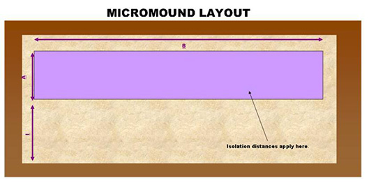
Basal Loading= The Overall Sand Area B (A+I)
The Basal Loading Rate is assigned by the soil scientist (based on table 1)

Example: soil scientist assigns .4 gal/ft2/day
400 gal/day
.4 gal/ft2/day
=1,000 ft2
this is the minimum amount of basal sand required
Horizontal Linear Loading= Minimum length of sand (including the side berms)L

Horizontal Linear Loading Rate
The horizontal linear loading rate is assigned by the soil scientist, based on table 1 of the alternate listing.
Example: soil scientist assigns 4 gal/ft/day
400 gal/day
4 gal/ft/day
=100 Feet
This is the minimum length of sand from toe of sand berm to toe of sand berm (L)
Sand Bed Loading= the sand located directly under the tubing, not including the side berms (BXA)

Sand Bed Loading Rate
The Sand Bed Loading Rate is located in the alternate listing.
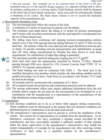
***The maximum possible sand bed loading rate is .75 apd/ft2
Example:
400 gal/ day
.75 gal/ft2/day
= 533ft2
This is the minimum amount of sand required under the tubing.
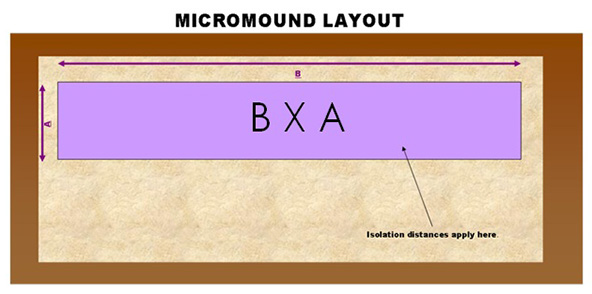
Isolation Distances
- Apply to the sand bed area only (BXA)
- All chapter 73 isolation distances +2′
- Example : 12′ to property line
- Example: 102′ to well

Down Sloping Sand Berm
The extended sand berm from the down slope side of the sand bed to the toe of the sand berm (l)
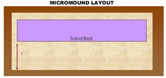
Down Slope Berm
To determine the downlsope sand berm, you must first determine the height of the mound.
Height of mound=
Sand under the tubing +
2″sand over the tubing +
12″ of top soil
Sand under the tubing:
12″ = Primary Pretreatment
8″ = Secondary Pretreatment
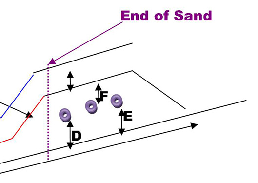
Depth of Sand
Depth of Sand: D/E+F+H
Assume: 12″ below tubing (D/E)
Depth of Sand: 12″ + 2″ +12″
Total Depth= 26″
You will also need the Downslope Correction Factor.
assume a 6% slope = 1.22 correction factor
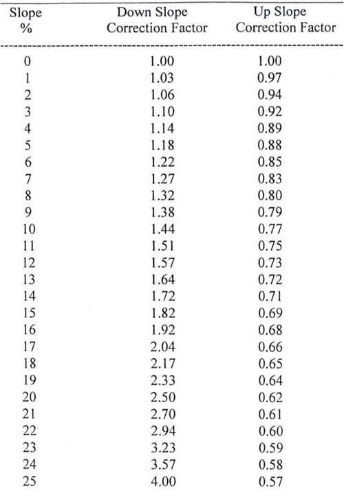
I=(N+H) X 3 X Slope Correction / 12
N=Height of sand (14″)
H=Height of Soil Cover (12″)
3= 3:1
Slope Correction = 1.22
I=((14″+12″) X 3 X 1.22) / 12
I= (26″X 3 X 1.22) /12
I= 7.93 feet
I=8′ Minimum (always round up)
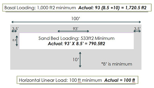
Example Summary
- Basal Loading: Minimum 1,000ft2
- Overall sand area
- Horizontal linear Load: Minimum 100ft
- Length of sand including side sand berms
- Sand Bed Loading: Minimum 533 ft2
- Sand area under the tubing
- Downslope Sand Berm: Minimum 8′
- Sand berm from edge of sand bed to toe of sand berm
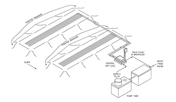
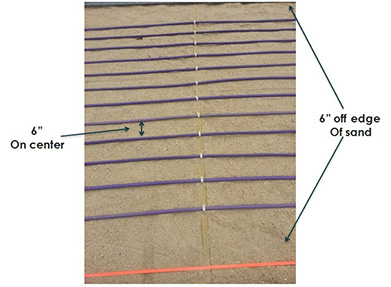
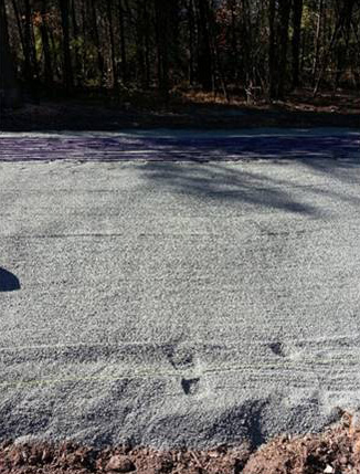
Let’s Build This Micromound
 Let’s put some tubing on this micromound. We should put .5 to .75 foot spacing over the mound.

Special Side Notes
- Minimum of 2 zones required on all system designs
- The zones can be different sizes
- different number of runs per zone
- The lateral lengths, within a zone, should be 20% of each other
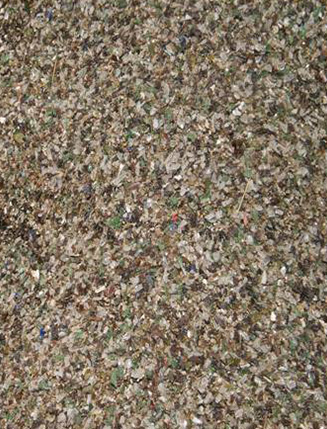
Look for a sand specification in the design.
The alternate technology listing specifies the sand requirement

Special Sand Notes
- The alternate listing sand specification for micromounds is the same as the sand used for sand mounds except <5% should pass through the #200 sieve.
- The alternate listing state that cement concrete sand type A or ASTM C-33 concrete sand is preferred.
Important Calculations to Verify
- Dosing Rate– the rate at which the effluent discharges from the tubing (apm)
- Field Flush Flow Rate– the rate in which the tubing is flushed (apm)
- Total Forward Flush Rate– dosing rate + field flush flow rate (must not exceed 15 gpm)
- Vertical Lift– the elevation difference between the off float and the highest/lowest drip emitter
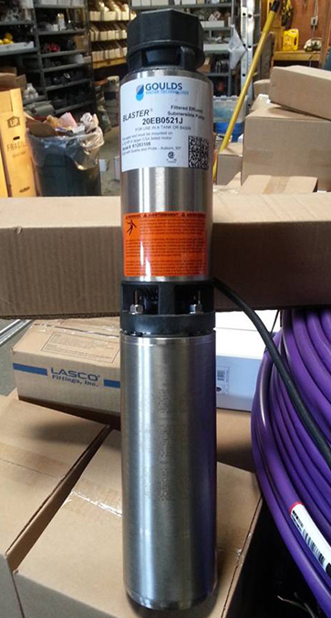
- Pump Size– based on the maximum head loss from all calculations
The Dosing Rate
LF of tubing/ distance between emitters X .61 gph / 60 min / hr
Using our example, zone 1:
8 runs at 89′ each
Total: 712 Linear Feet
712ft / 2 ft X .61gph / 60 min / hr
= 3.62 gallons per minute
Field Flush Flow Rate
Number of lateral connections X 1.6 gpm
Using our example:
8 runs = 4 laterals
4 laterals X 1.6 gpm
=6.4 gpm
Total Forward Flush Flow Rate
= Dosing Rate + Field Flush Flow Rate
Based on our example:
3.62 GPM + 6.4 GPM
= 10.02 GPM
**this must equal less than 15 GPM to use a residential Hydraulic unit
The vertical lift can be verified by the Hydraulic Profile.
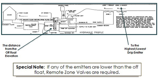
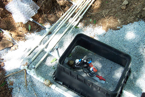
Remote Zone Valve
Pump Sizing
- Calculate total head loss per zone
- Calculate the disc filter back flush head loss
- The larger determines the pump size
**the filter disc filter back flush head loss is always 124.16 feet.

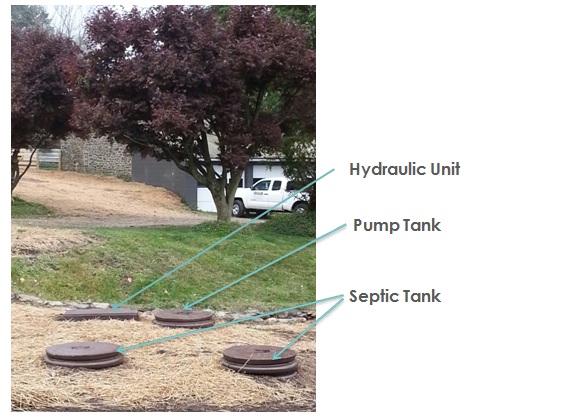
Tanks
- Septic Tank (12″ sand under tubing)
- Chapter 73.31 regulations
- Cylindrical tanks meeting Ch. 73.31 are permissible
- Vertically aligned circular tanks are not permitted
- Secondary treatment technology (8″ sand under tubing)
- Permit application must include a letter from the drip equipment manufacturer recommending its use and compatibility.
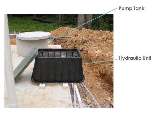
- Pump Tank
- The working volume >=60% peak design flow
- Typical 3-4 bedroom home = 1000-1500 gallon tank
The effluent filter is recommended
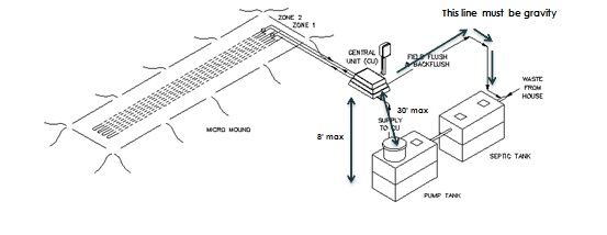
Hydraulic Unit
- < = 30′ Horizontal from pump
- < = 8′ Vertical from off float
- Gravity backflush line
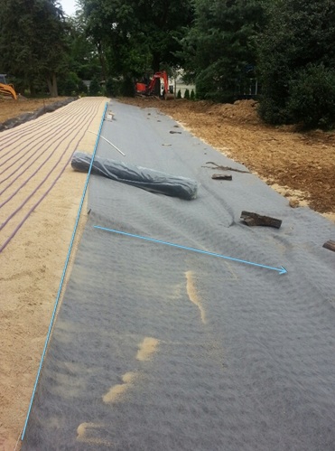
A Common Option
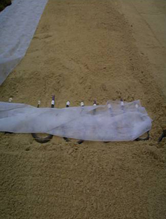
Example from the Field
Stakeout Inspection Prior to Permit Issuance
- The 4 corners of the Basal Area should be stakes
- Check to make sure that they are on contour
- You will avoid a situation figured below
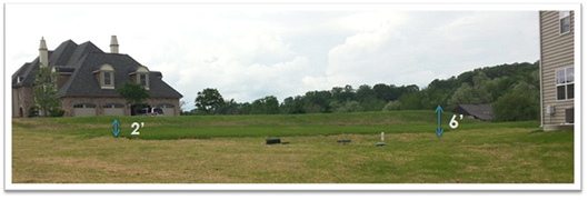
Very Important
Just because American Manufacturing Company has reviewed the design, does not mean a complete review by the SEO is not necessary.
Facts
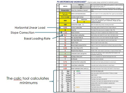
- 4 Bedrooms (500 GPD)
- 8% slope
- .4 gal/ft2/day Basal Loading Rate
- 4 gal/lf/day Horizontal Linear Loading Rate
- .75 gal/ft2/day sand bed loading rate
- Septic tank effluent
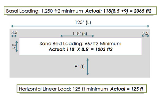
1. What is the Minimum amount of Basal sand area needed B ( A+I)?
500 gal/day
.4 gal/ft2/day
=1,250 ft2
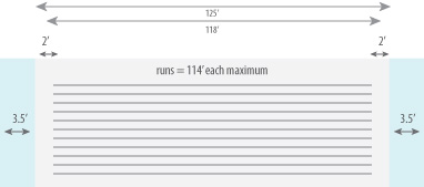
2. What is the minimum length of the basal sand area required, including side berms (L)?
500 gal/day
4 gal/lf/day
=125 linear feet
3. What is the minimum amount of sand required under the tubing (BXA)?
500 gal/day
.75 gal/ft2/day
=667 ft2
4. What is the minimum length of the downsloping berm (l)?
total depth of sand = 26″ (12″+2″+12″)
(26″X3X1.32)/12
=8.58 feet
= Round to 9 feet
5. What is the maximum run length that would work on this mound?
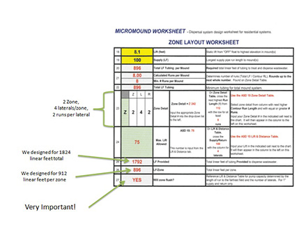
6. Based on a mound with 16 runs (8 runs per zone) @ 114′ each, what is the dosing rate for each zone?
8X114 if = 912 if/zone
912 if / 2ft X .61 gph / 60 min / inch
=4.63 gallons per minute
7. Based on this same scenario, what is the field flush flow rate for each zone?
8 runs per zone= 4 lateral connections
4 X 1.6 gpm
=6.4 gpm
8. What is the total forward flush flow rate?
Dosing rate + field flush flow rate
4.63 gpm + 6.4 gpm
=11.03 gpm
will this scenario work? YES! 11.03 gpm < 15 gpm
Final Item
Two different listings exist for the micromound.
- American PER-RITE micromound
- JNM-ACT SAS mound drip
Calculations in this class were that of the PERC-RITE micromound.
Listings for American and JNM are separate and distinct; thus the purpose of the separate listings.
KEY POINT: If you are permitting a system design, make sure that the equipment that goes in the ground matches what is called for in the design.
no substitutions without re-design!