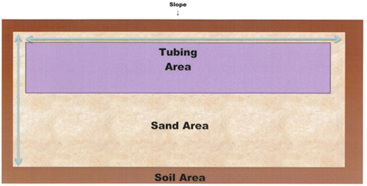
What is a Micromound?
On Contour at-grade bed with:
- Sand (8-12″)
- Netafim Drip Tubing
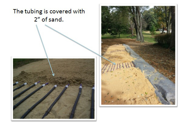
- More Sand (2″)
- Soil (12″)


When is a Micromound Used?
- When slopes are between 0 and 15 percent
- When soils are greater than or equal to 10″ to SHWT and 16″ to rock
- When there is sufficient length to contour
The American Perc-Rite Alternate Listing
In this listing PA DEP specifies the design, permitting and installation requirements.
Permitting Requirements
SEO may issue the permit if he/she has completed a department sponsored training course on this specific technology or received review delegation in writhing from the department. If neither of these occur the design must go to your regional department for review and comment before issuing the permit.
Manuafacturer’s Representative’s Responsibilities
They must be present to oversee the installation of the system until the installation contractor has completed a training course (usually field experience); and has successfully installed a sufficient number of drip micromounds under the direct supervision of the manufacturer’s representative.
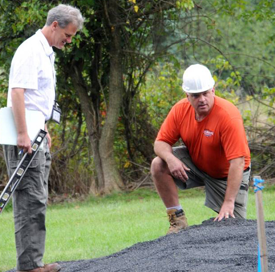
SEO Installation Inspection Responsibilities
- Ask “Are you a certified installer?”
- Verify this with the manufacturer’s representative
- Very Important: Just because the manufacturer’s representative is on site, this does not excuse the SEO from proper inspection of the system installation.
Two different listings exist for the Micromound:
- American PERC-RITE micromound
- JNM_ACT SAS mound drip
Components included in a design package must meet the components during installation.
Listings for AMC and JNM are separate and distinct for that reason.
KEY POINT: Make sure that the equipment that goes in the ground matches what is called for the design.
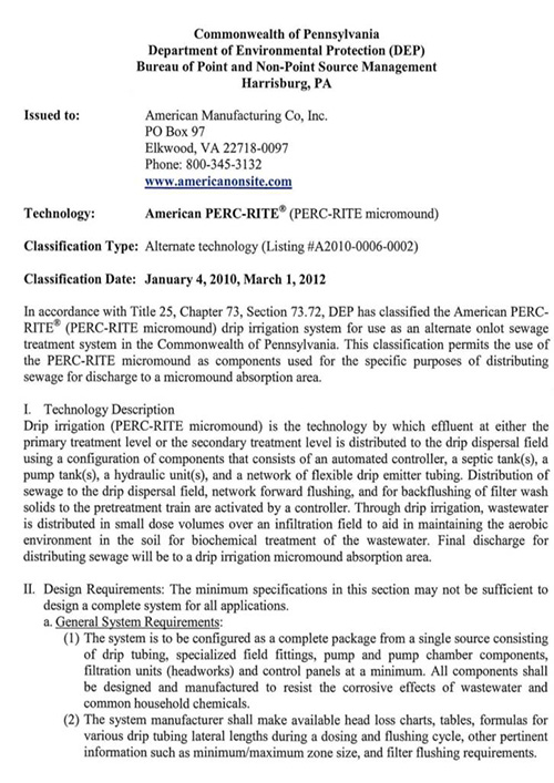
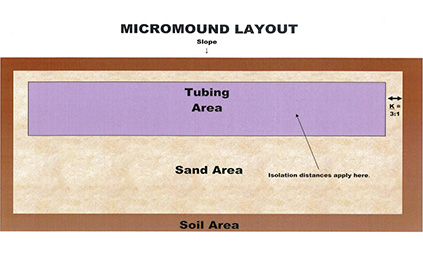
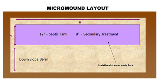
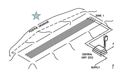
Typical Micromound Layout

Split Mounds
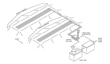
Other Configurations

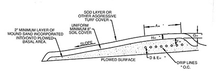
Profile of a Micromound
 3 Bedroom = 100′ X 16′
4 Bedroom = 125′ X 20′
5 Bedroom = 150′ X 20′
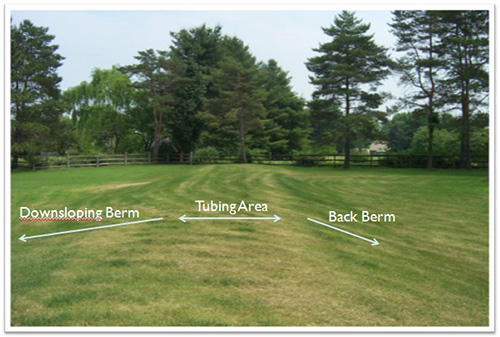
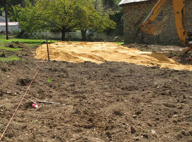
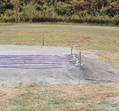
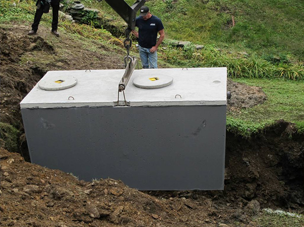
Completed Installation
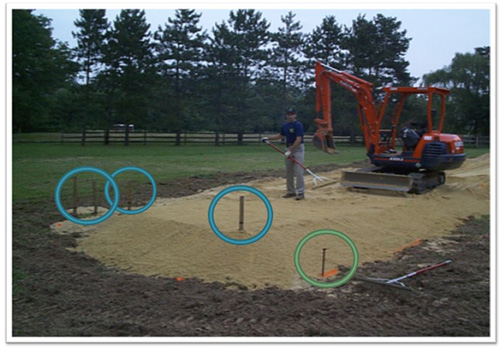
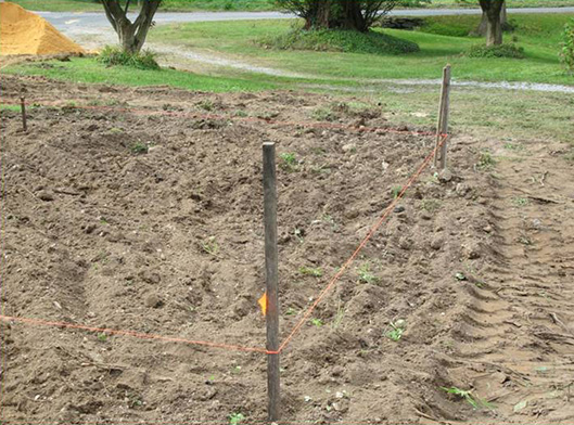
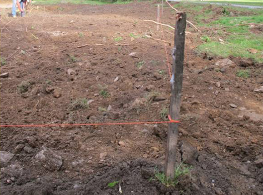
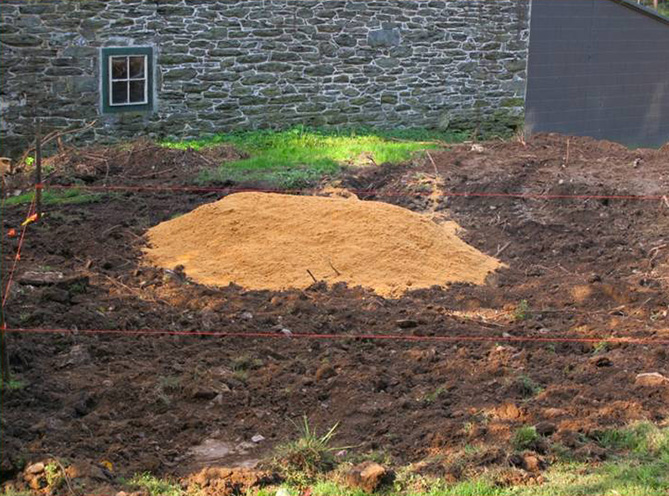
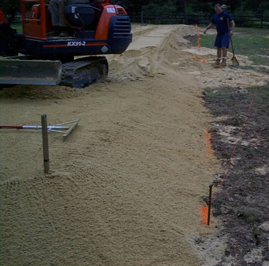
The Stakeout Inspection
– Typically is done before permit issuance
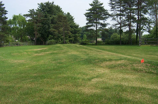
– The micromound must follow the contour of the land

**proper stakeout inspctions can prevent situations like this
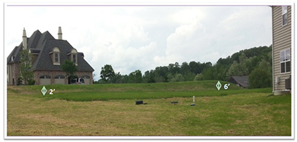
Stakeout helps with sand placement and depth verification
Soil Moisture Inspection
SEO Inspection
- Area may not be scarified until a soil moisture test has been completed
- Soil must crumble at the 6″-8″ plow depth
- Must prevent soil “smearing” (just like an elevated sand mound)
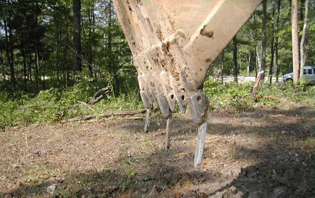
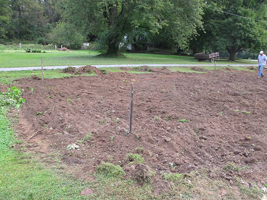
Scarification
Purpose
- Roughen the surface to allow for better infiltration into the top soil
- Provide a more transitional contact between the sand and soil
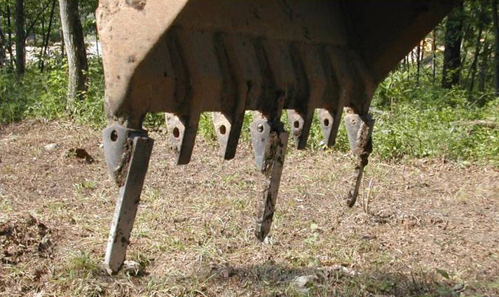
How To
- Most preferred : chisel teeth mounted to backhoe (great around stumps)
- Next, chisel plow behind a tractor (open sites)
- Last, backhoe bucket with sharp teeth (time consuming)
- Important: Rototillers are prohibited
Key Point: Scarification must be with the contour of the land.
What to Scarify
Entire basal area
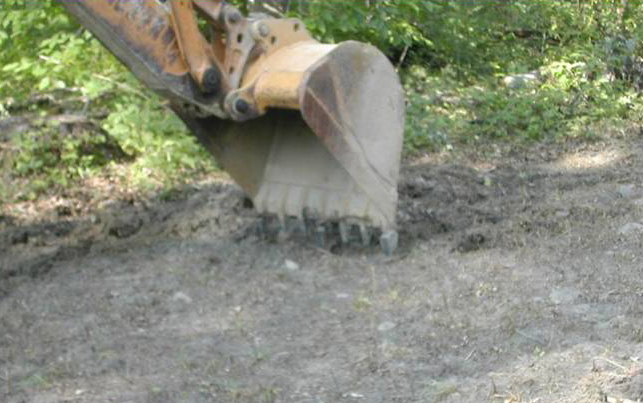

Scarification is complete

The Site is Prepared
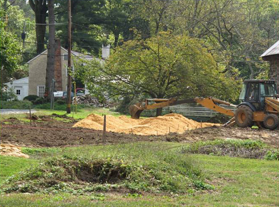
Sand Placement
The sand specification is found in the alternate technology listing.

This is not the same as an elevated sand mound
- The alternate listing sand specification for micromounds is the same as the sand used for sand mounds except <5% should pass through the #200 sieve.
- The alternate listing state that cement concrete sand type A or ASTM C-33 concrete sand is preferred.
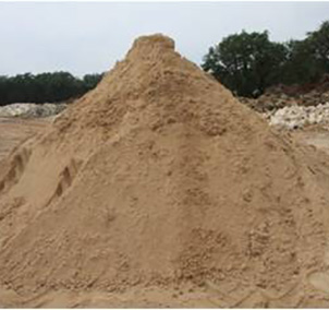
Different Types of Sand
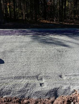

The Sand
- Once the site is scarified, the sand must be placed before it rains
- The sand must not be mixed, but applied so it naturally fills the voids
- The sand must be placed with a backhoe and leveled
- This is not a flat topped sand bed, it is to be even, along contour and sloping with grade
Depth of Sand Inspection
Sand depth is specified in the design:
8″ = Secondary Treatment
12″ (or more) = Septic Tank Effluent
Sand Bed Depths

The Contractor will begin to place and spread the sand
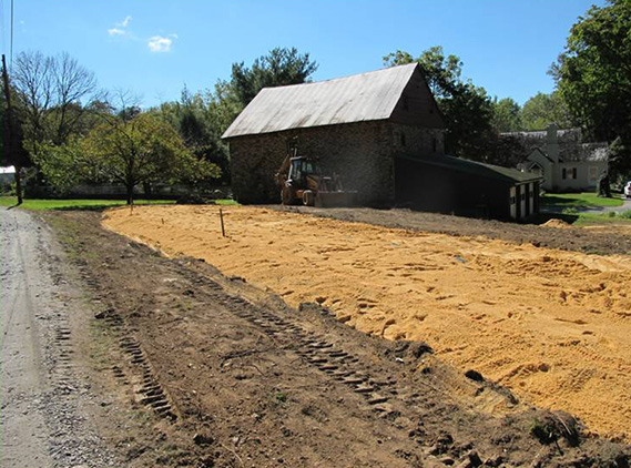
After the sand placement is complete the sand depths should be verified by the SEO
Don’t Forget
- Micromounds are on contour low profile mounds (their tops should not be flat!)
- All mounds must be constructed with minimum 3:1 berms (other than the down sloping sand berm)
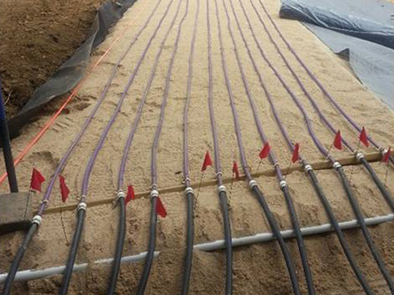
Tubing Placement Inspection
Design must specify:
- Number of tubing runs
- Length of tubing runs
- Spacing between the tubing runs
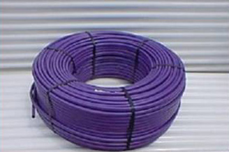
Netafim Tubing
Only tubing manufactured by Netafim has been shown to meet the requirements of the alternate listing. No substitutions of other drip tubing is permitted.
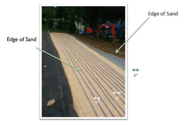
Run= Length of Tubing Across Contour
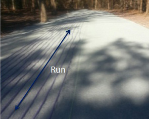
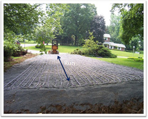
As per the alternate listing:
Tubing Spacing = 6″ – 9″
(as specified by the designer)
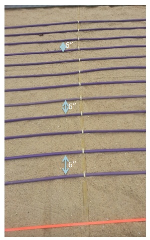
Tubing Spacing
SEO’s must verify:
- Number of runs
- Length of runs
- Spacing between runs
At This Point
- The alternate listing directs the SEO to the specifications provided by the manufacturer.
- Some of the following items may be manufacturer’s specifications, not clearly stated in the alternate listing. I will decipher between the two when possible.
Cold Climate Installation Techniques

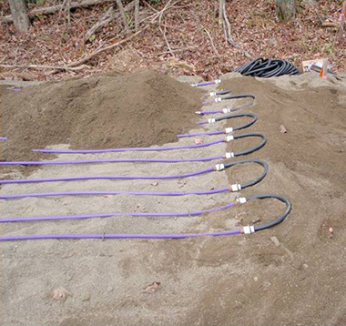
Lateral = One or more runs looped together
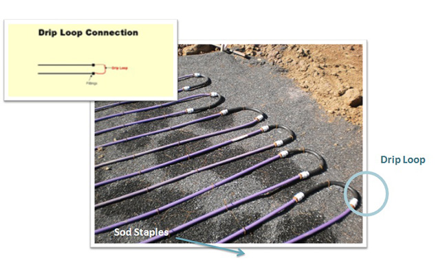
The Loop Ends
Must be elevated with 2″ with pressure treated wood, bricks, or firm sand bed.

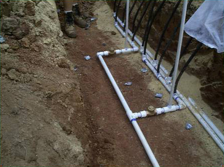
Manifold Construction
Manifolds are used to deliver the effluent to a zone from the tanks via the supply lines.
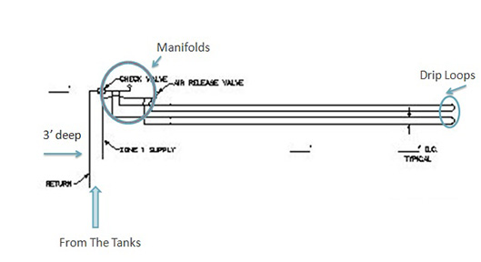
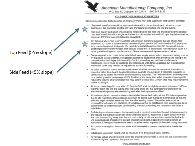
Top Feed Manifolds
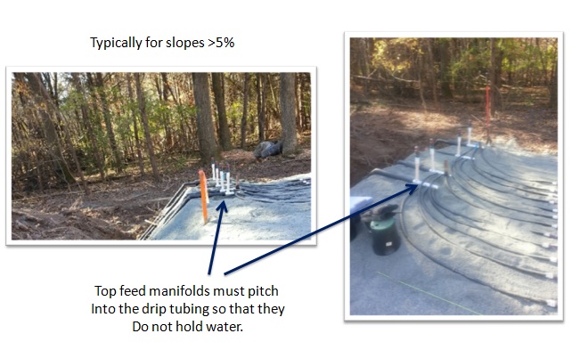
Side Feed Manifolds
Typically for slopes <5% slope
Cold Climate Installation Techniques
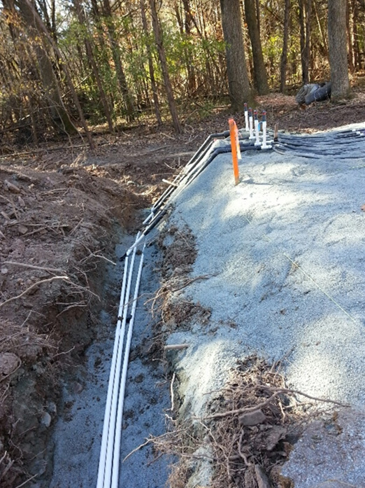
Verify Depth of Conveyance Lines
Must be below local frost line (typically 3′ below grade)
Cold Climate Installation Techniques

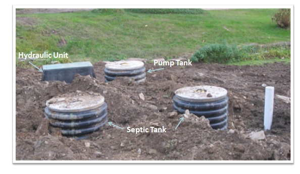
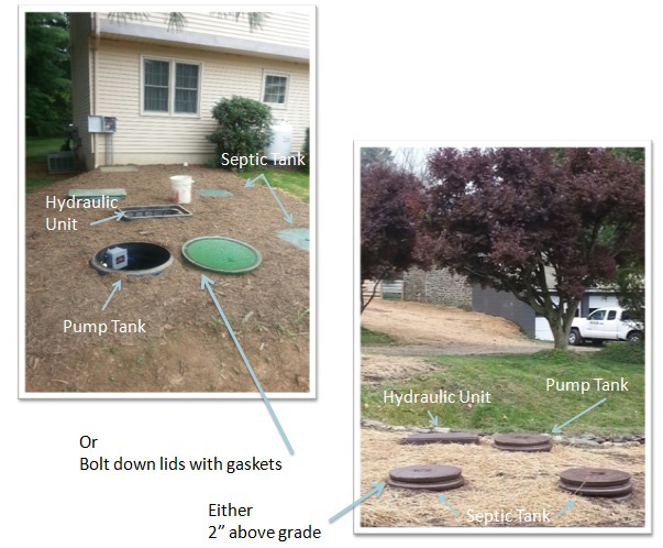
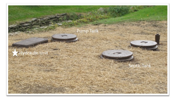
After the mound is installed, but before start up, the contractor must:
- Install septic tank
- Install pump tank and components
- Install hydraulic unit (central unit)
- Install supply and return lines to the mound
- Install and wire control panel
Septic Tank Inspection
No different than your standard septic tank inspection
- Primary treatment (>/=12″ sand)
- Concrete tanks must be dual compartment rectangular or 2 rectangular tanks in series
- And/or, must conform to meet the requirements of section 73.31
- Cylindrical tanks meeting section 73.31 may also be used
- Vertically aligned circular (round) tanks are not permitted
If Secondary Treatment is necessary due to an 8″ sand bed depth
The permit application must include a letter from the drip system manufacturer stating that it is compatible with the PERC-RITE drip micromound
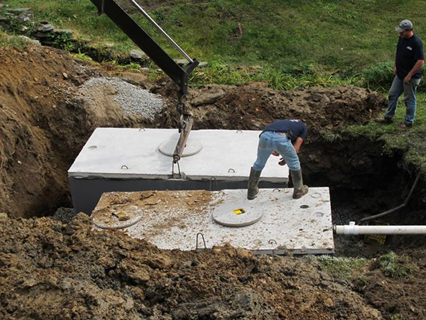
Septic Tank Installation
Check the design for an effluent filter requirement
this is recommended, not required
Pump Tank
1,000 Gallon- 2,000 gallon for residential
The working volume >=60% design flow
Requirements of the Pump Tank
- Audible and visual high-water alarm set with 25% of the peak daily flow as reserve volume above the high water alarm
- Low-water cutoff device (the off float) to prevent damage to the pump during low water conditions
- This float should be separate from the timer enable device (the dose float)
- A watertight access to grade is required (VERY IMPORTANT)
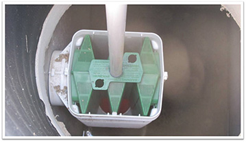
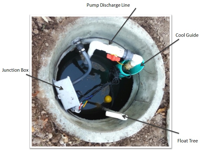
Pump Tank Innards
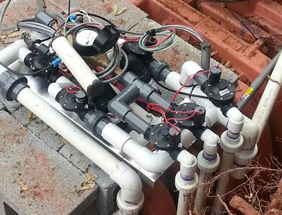
Hydraulic Unit Specifications
As per the Alternate Listing:
- 2 disc filters are required
- They must backflush independently of each other
- The residual water must return to the head of the pretreatment train.- Sometimes you will see it return to a settling tank or the first compartment of a dual compartment dosing tank.
- The Hydraulic Unit must be protected from freezing temperatures (i.e. heater strip with thermostat).
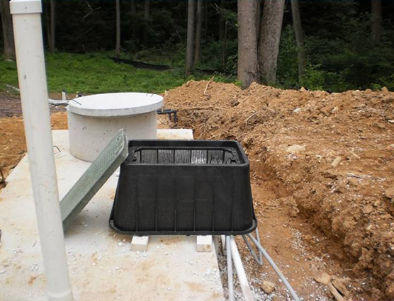
Hydraulic Unit
Other H-Unit Placements

Daylight Drain the Hydraulic Unit
To grade or into a French drain
Cover end with slotted cap to keep out rodents
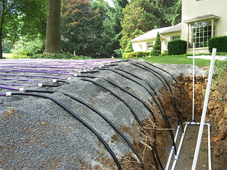
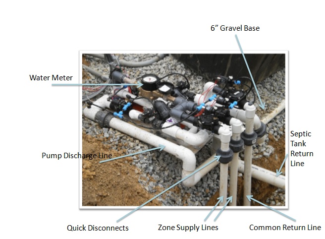
Supply & Return Lines
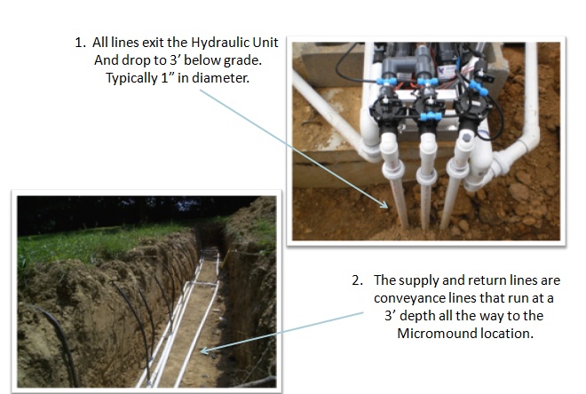
Conveyance lines feed the top feed or side feed manifolds

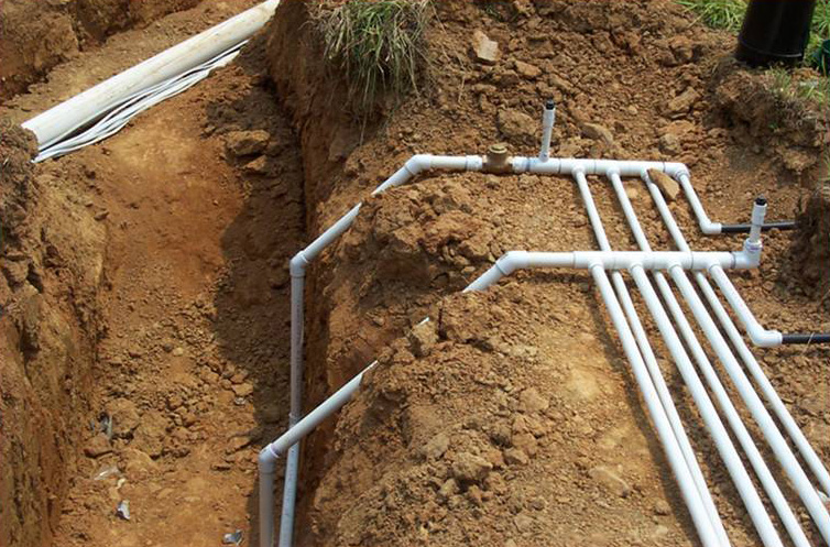
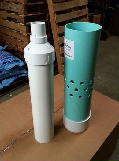
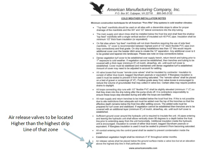
Air Release Valves
Purpose:
- The help the system to quickly pressurize when the pump turns on
- To help the system’s tubing to quickly drain when the pump shuts off.
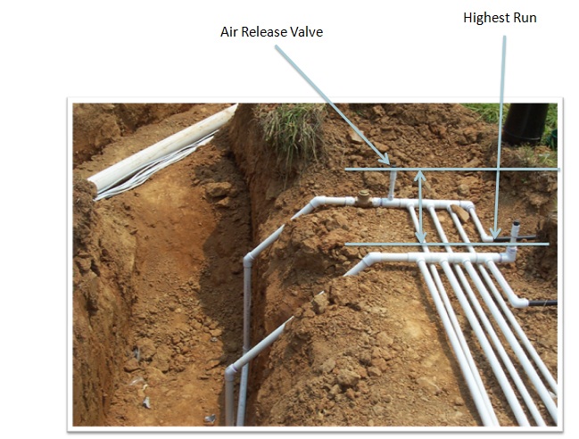
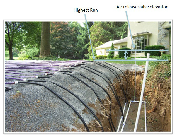
Location:
- Top Feed: one on both the supply and return manifolds (higher than the highest piece of drip tubing for that zone)
- Side Feed: one on each of the return lines (higher than the highest piece of drip tubing for that zone)
Top Feed Example
Side Feed Example
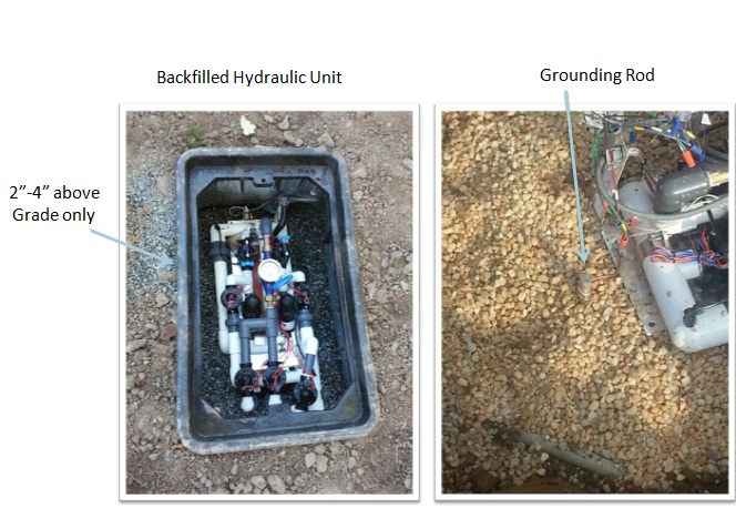
Before Finish Grade
Final Grading
Manufacturer’s Recommendation
Control Panel
Installed on home or installed in field
**panel must be 3′ minimum above ground
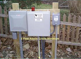

Wiring Performed by Electrician or Experienced Contractor (see local code)
Ground control panel locally via a ground rod or an approved grounding method.

Is an Electrical Inspection Required?
Installation is Complete:
- System should be uncovered for the system start-up inspection. This includes:
- PVC SCH40 supply and return lines
- Manifold Connections
- Loop ends
- All other pressurized plumbing
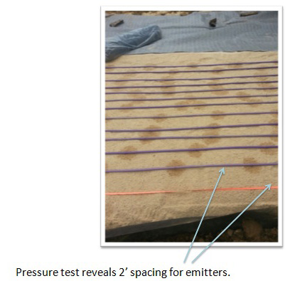
Time For System Start Up Inspection
- Performed by the manufacturer’s representative. SEO should be on site.
- The system is pressure tested for leaks, clogs and proper amount of tubing.
- Upon a successful start-up, the system can be covered.
Start Up Rates To Record
Dosing Rate
- The amount of effluent discharged from the emitters based on the amount of tubing on the mound
- Gallons Per Minute
- Too fast= leak or too much tubing
- Too slow= clog or not enough tubing
- Must be +/- 10% of the design calculation
Additional Rate to Record
Field Flush Flow Rate
- The rate at which the tubing is flushed
- Expressed in gallons per minute (GPM)
- Must meet, or exceed, the design minimum
Cover and Final Grade Inspection
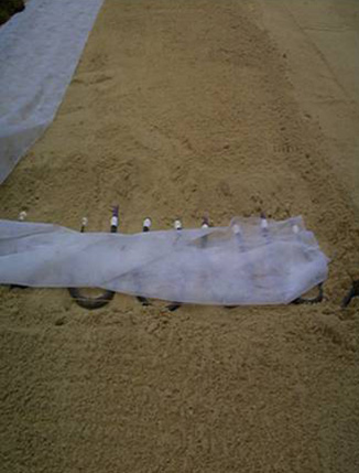
Verify Sand Cover
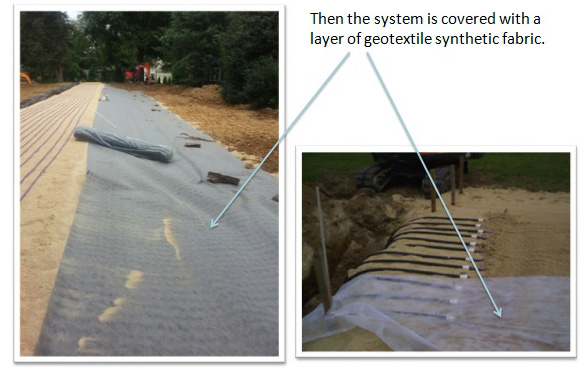
Verify Geotextile Layer
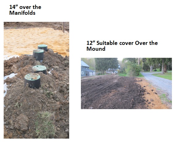
Verify Mound Cover
- 12″ of suitable cover over the top of the micromound
- 8″ of suitable cover over the sides and shoulder of the micromound
- Cover the downloping berm and extend the toe
Final Grade Inspection
Surface water must move away from the micromound (and tanks) and may not accumulate on top, or up slope, of the mound
 Vegetation
- The area must have seed and straw immediately to avoid erosion
- Sod is recommended
- Aggressive turf must be established and maintained
- Erosion control may be necessary on some sites with steep slopes.
Look for Good Winter Cover
Thick winter cover of straw or mulch is necessary for late Fall installations.


A Good Winter Tank Protection
Protection
Remind the installer that good fall protection will protect against harsh winter weather
Cold Climate Installation Techniques

If it is on the Design, it Must Happen
Examples
- Curtain drains
- French drains
- Effluent filters
- Tank coating
- Drain to daylight
After the System Startup
30 Day Homeowner Meeting
The Manu. Rep. must meet with the property owner within 1 month of system start-up and/or occupancy of the dwelling (and with the SEO upon request.)
- Instruction of system operation and maintenance
- Locations of all parts of the system
- Caution notice regarding zone disturbances
- Explain the automatic alarm system
- Statement requiring that the Manu. Rep. be contacted if the alarm system is activated