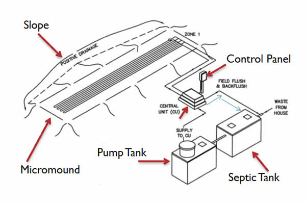
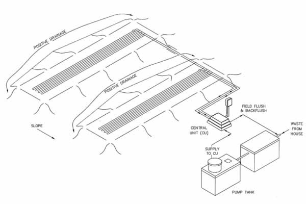
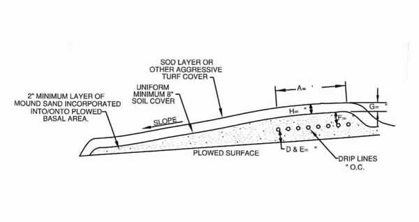
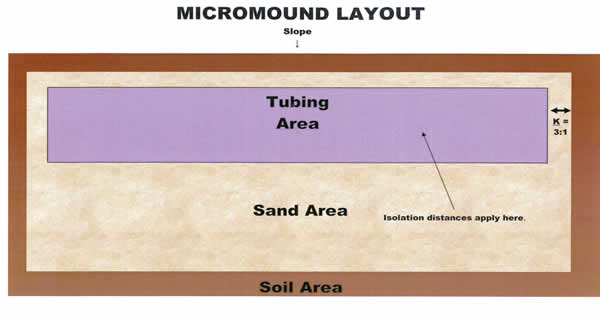
Micromounds are on-contour at-grade bed with sand (8″-12″), netafim tubing, more sand (2″), and soil (12″). They are primarily used when slopes are between 0 and 15 percent, soils are greater than or equal to 10″ to SHWT and 16″ to rock, and there is sufficient length on contour. In the American Perc-Rite Alternate Listing, the PA DEP specifies the design, permitting, and installation requirements. This article will guide you through the steps of micromound installation, and is a resource to be used on it’s own or with our PA Micromound Installation Class.
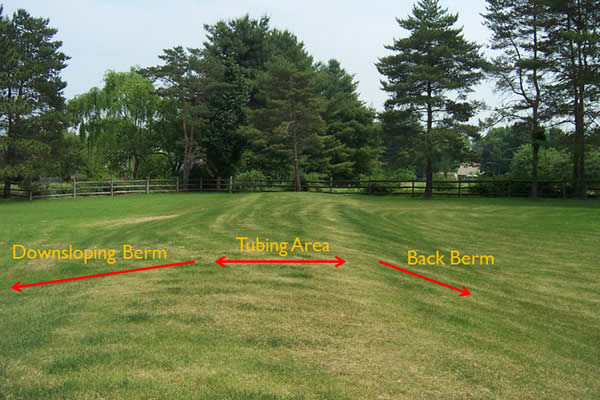
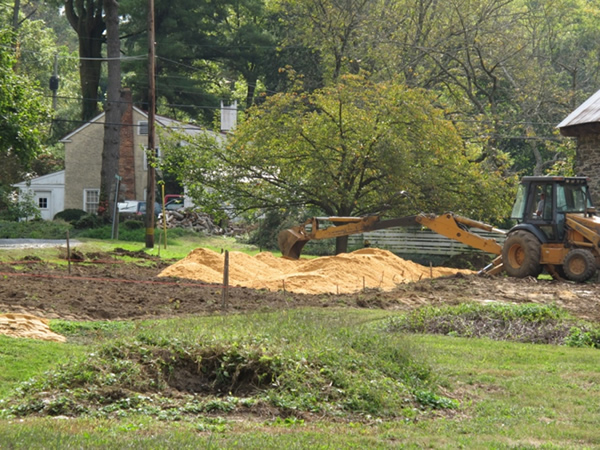
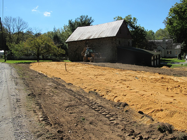
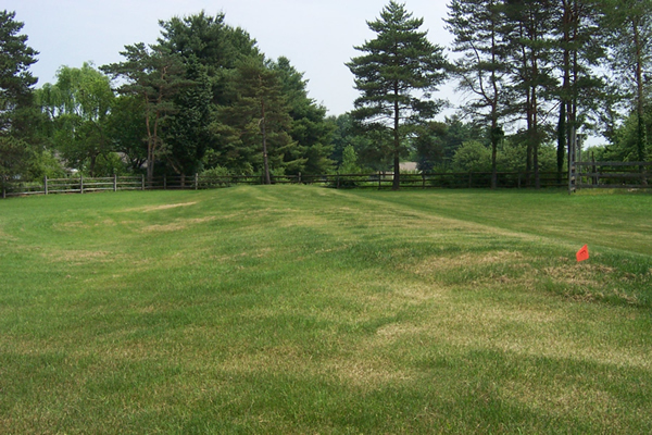
Micromound Layouts
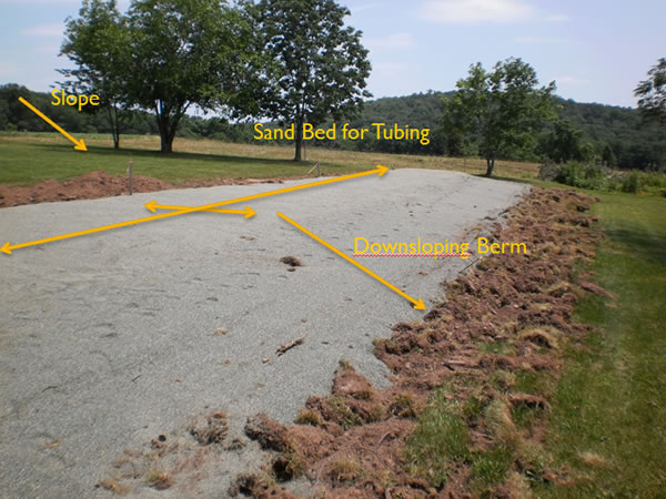
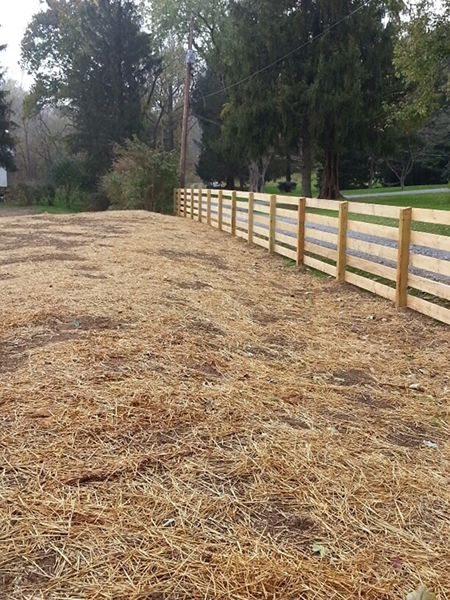
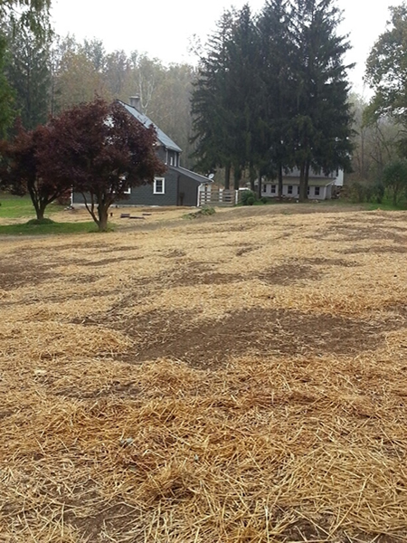
Site Preparation Steps
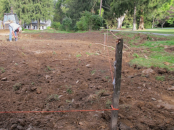
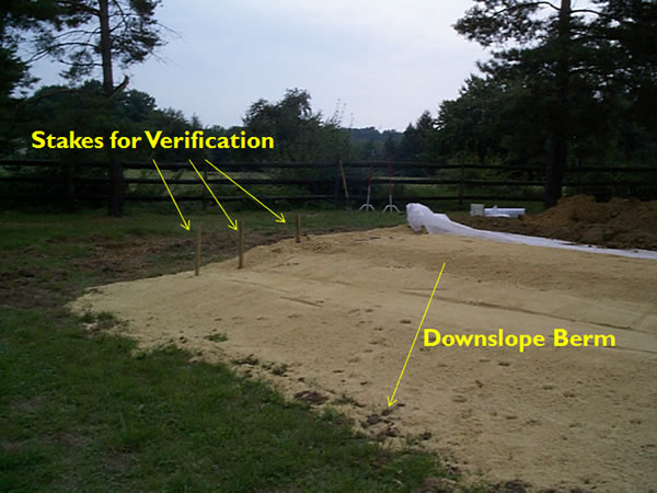
Step 1: Stakeout
- The micromound must be on contour.
Step 2: Prepare the absorption area.
- This includes the downsloping berm.
- Cut grass, trees, and shrubs close to the ground surface.
- If the micromound is being installed on a wooded site, make sure to rake leaf litter off of the site.
- Do not pull stumps out, remove top soil, sod, or boulders.
Step 3: Soil Moisture Inspection / SEO Inspection
- Area may not be scarified until a soil moisture test has been completed.
- Soil must crumble at the 6″ to 8″ plow depth.
- Must prevent soil “smearing.”
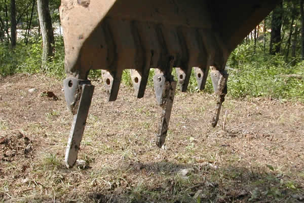
Scarification
The purpose of scarification is to:
- Roughen the surface to allow for better infiltration into the top soil.
- Provide a more transitional contact between the sand and soil.
What to scarify: Make sure to scarify the entire basal area (where it says “Sand Area” below).
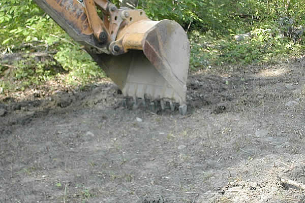
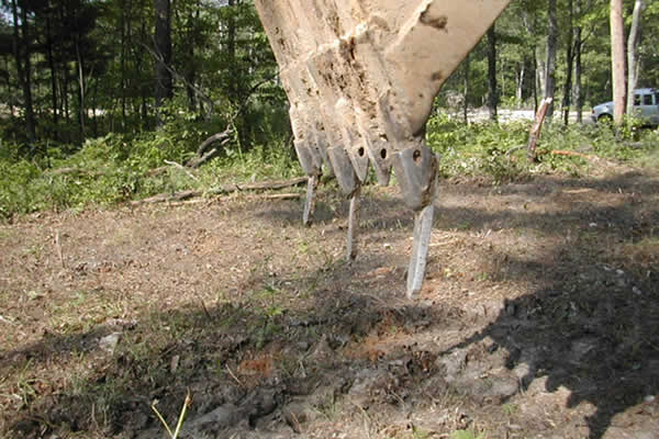
How to scarify for micromounds:
- Most preferred: chisel teeth mounted to backhoe (great around stumps).
- Next, chisel plow behind a tractor (open sites).
- Last, backhoe bucket with sharp teeth (time consuming).
- Important: Rototillers are prohibited.


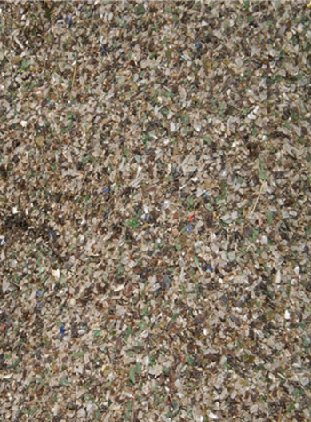
Sand Type
The sand specification is found on page 5 of the Alternate Technology Listing, under the Micromound Absorption Area (g). The quote is below:
“Sand used must meet the requirements specified by Section 73.55(c). Material passing through #200 sieve should be <5%. Cement Concrete Sand TYPE “A” or ASTM C-33 concrete sand preferred.”
Below are different types of sand that can be used:

Sand Placement
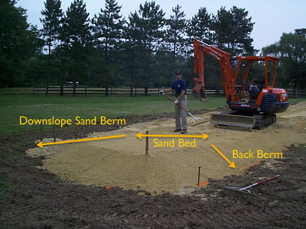
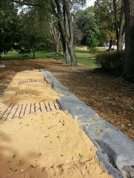
Once the site is tilled, the sand must be placed before it rains. Make sure to not mix the sand, but apply so that it naturally fills the voids. The sand should be placed with a backhoe, and leveled.This is not to be a flat sand bed; it is to be even, along the contour, and sloping with the grade.
Stake the sand boundaries and elevations:

Begin to place and spread the sand:
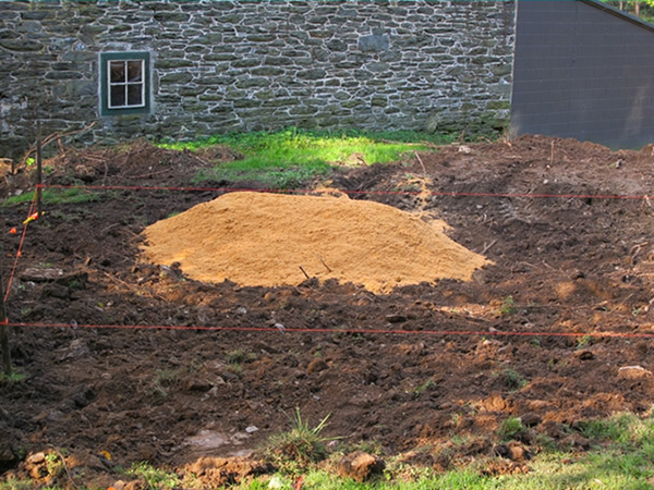

Continue to spread the sand until complete:
Stakeout with sand elevations, which helps with sand placement:
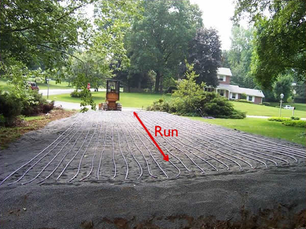
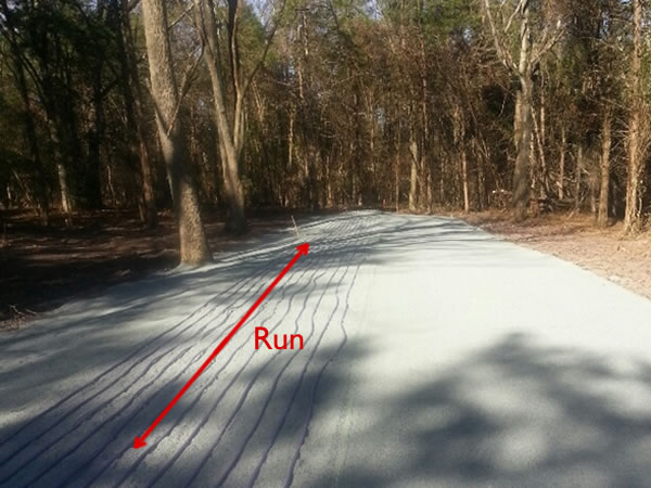
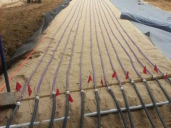
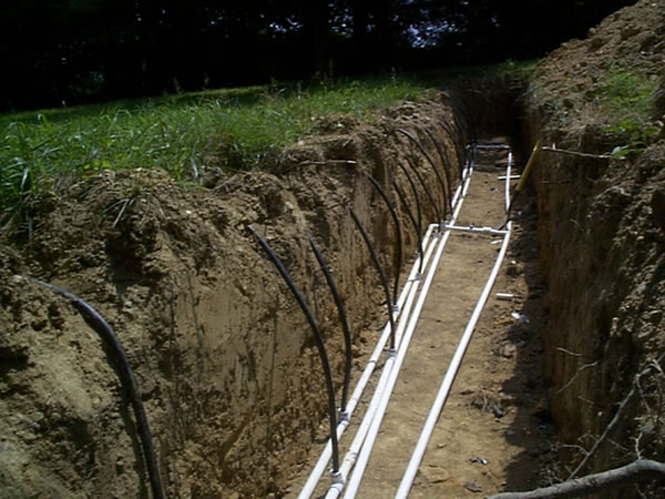
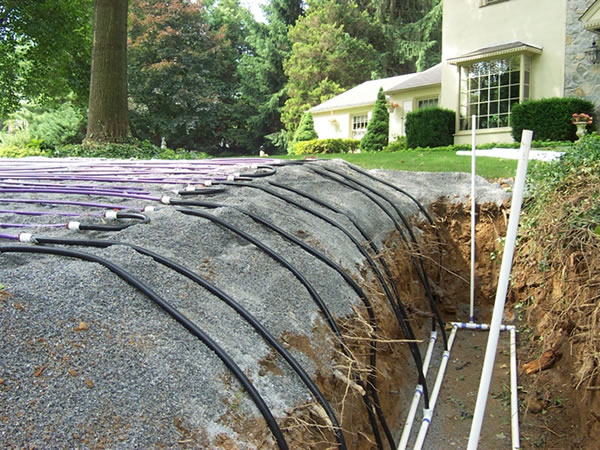
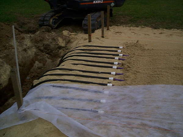
Tubing Placement
The micromound design must specify:
- Number of tubing Runs
- Length of tubing Runs
- Spacing between tubing Runs
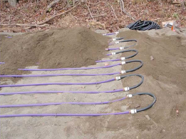
Run = Length of Tubing Across Contour:
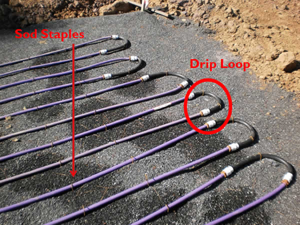
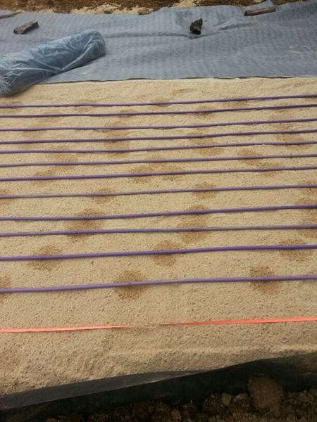
Tubing spacing should be between 1/2 foot and 3/4 foot apart (6″ to 9″):


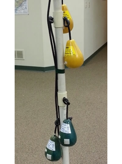
A lateral is one or more runs looped together: make sure to elevate the loop ends.
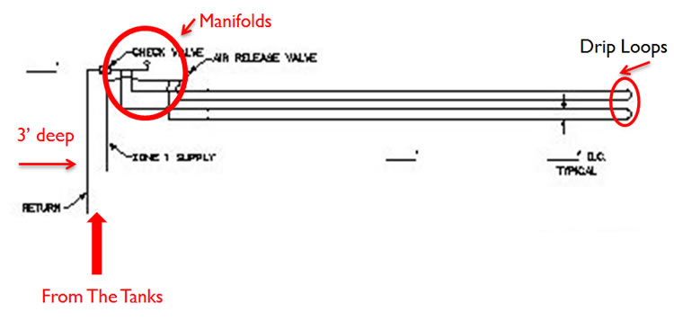
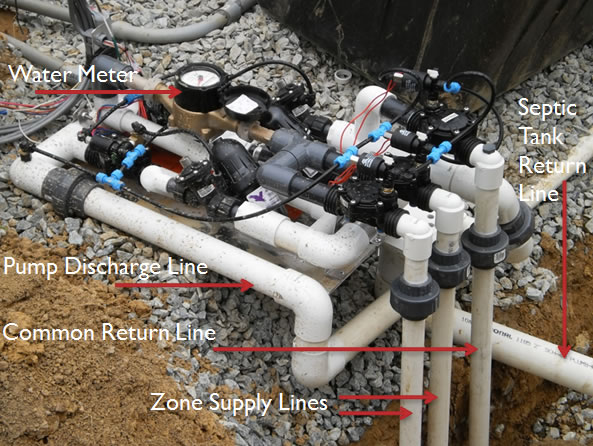
Manifold Construction
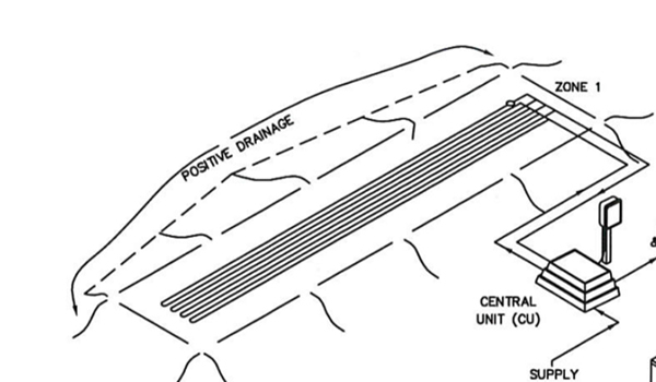
Manifolds are used to deliver the effluent to a Zone from the Tanks Via the Supply Lines.
Construct Manifolds: Top Feed.
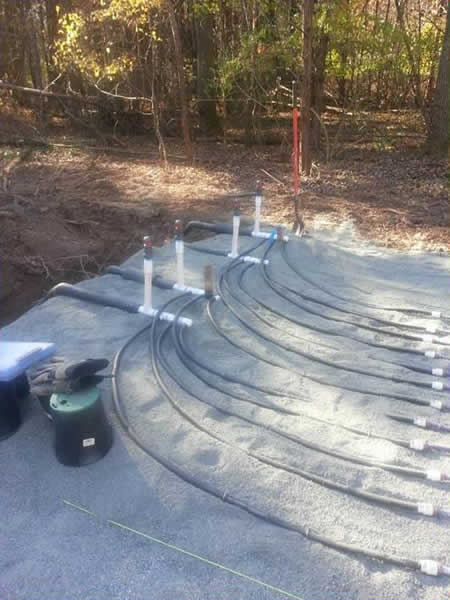
Construct Manifolds: Side Feed.

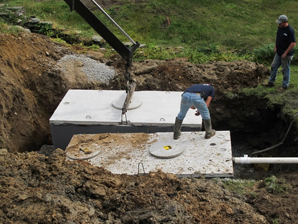
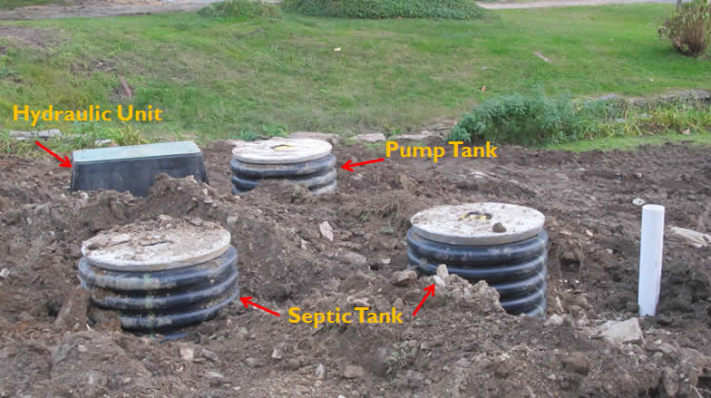
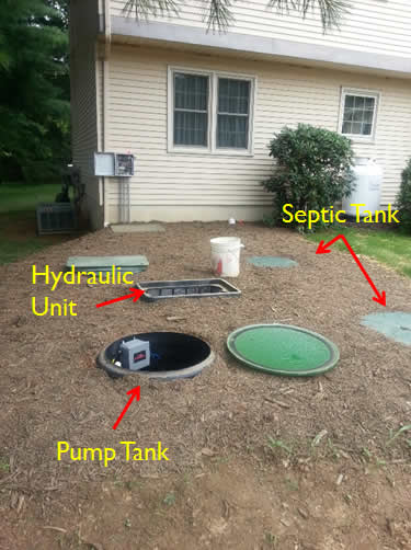
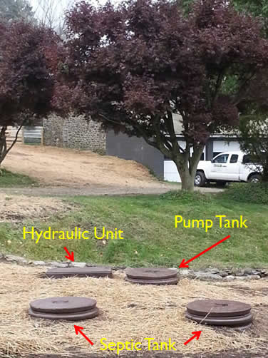
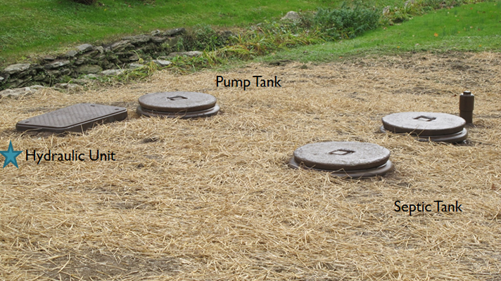
After Micromound Installation, Before Startup
- Install Septic Tank.
- Install Pump Tank and components.
- Install Hydraulic Unit (central unit).
- Install Supply and Return Lines to the Mound.
- Install and Wire Control Panel.
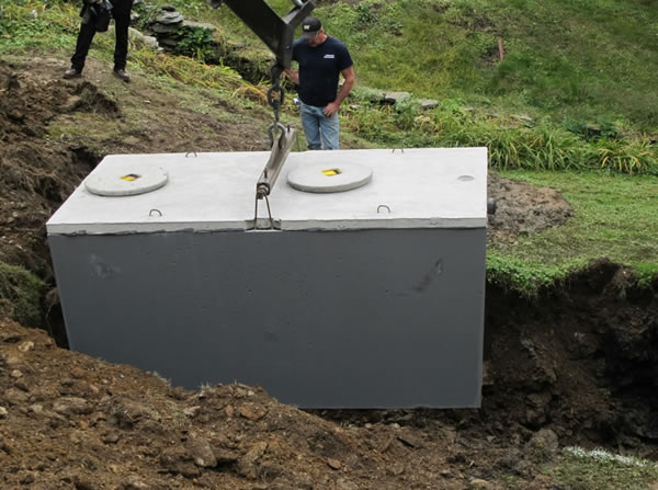
Septic Tank Installation
Chapter 73 Regulations require 8″ of sand for aerobic treatment and 12″ of sand for septic tank effluent.
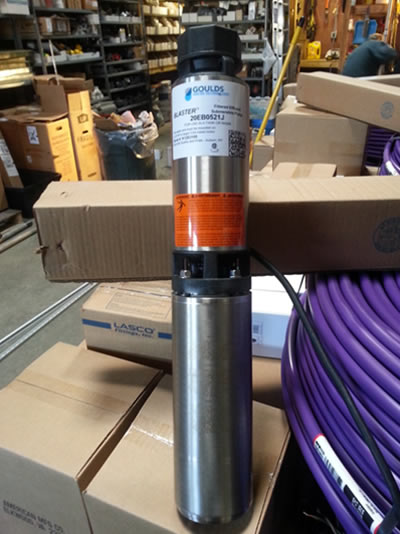
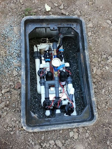
Install Pump Tank and Components
The pump tank can handle 1,000 to 2,000 gallons of effluent for residential purposes. The working volume is greater than or equal to 60% of design flow.
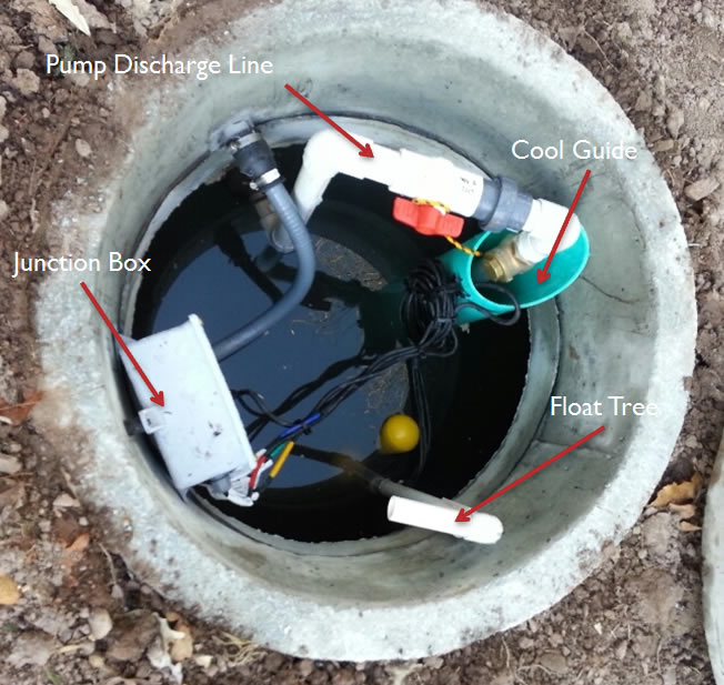
Pump tank innards:
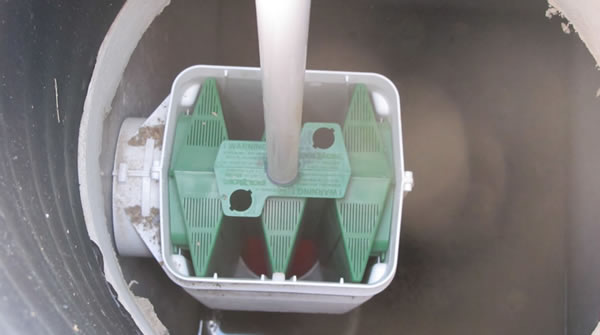
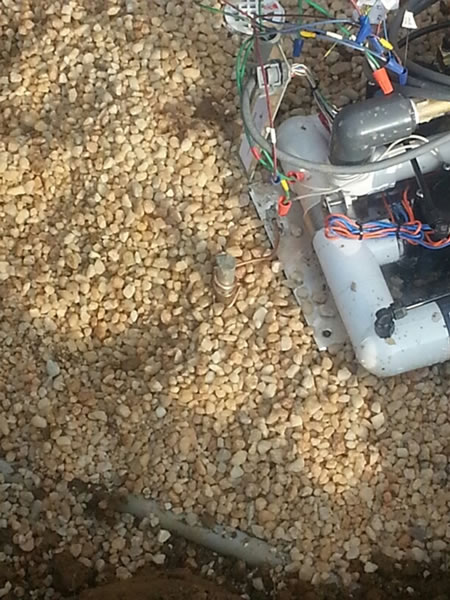
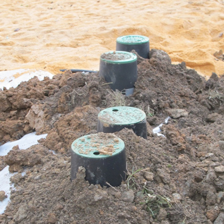
Hydraulic Unit
Backfilled Hydraulic Unit (left) and Hydraulic Unit Grounding Rod (right):
Final Grading
Before Final Grading:
After Final Grading:
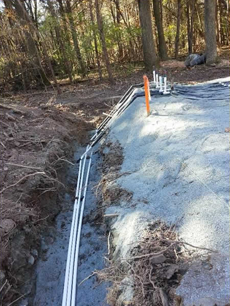
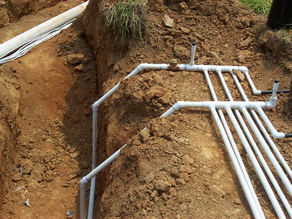
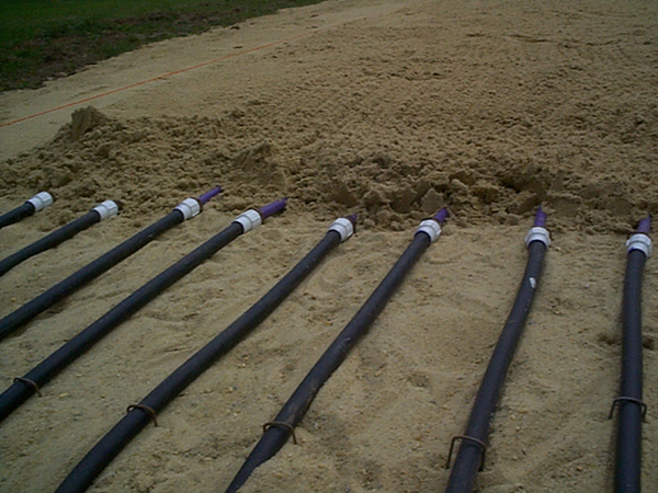
Supply & Return Lines
1. All lines exit the Hydraulic Unit and drop to 3’ below grade. Typically 1” in diameter (bottom left).
2. The supply and return lines are conveyance lines that run at a 3’ depth all the way to the micromound location (bottom right).
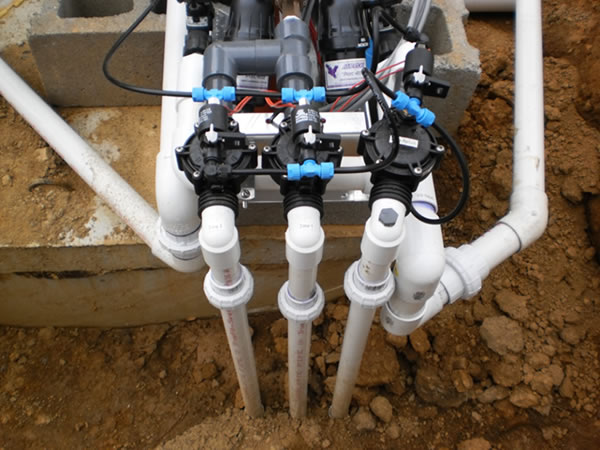
3. Conveyance lines feed the top feed or side feed manifolds.
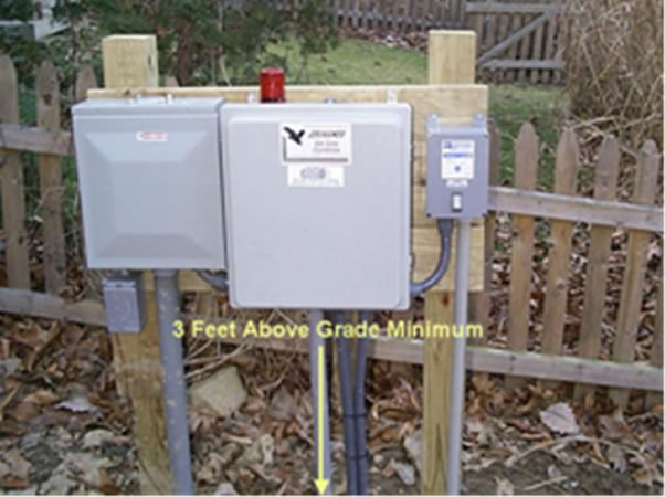
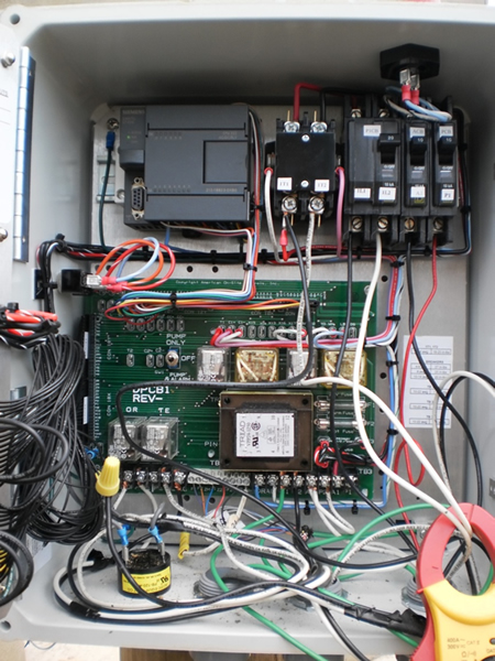
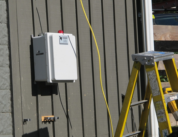
Control Panel
Installed on home (bottom left) or installed in field (bottom right).

Wiring Performed By Electrician
Ground the control panel locally via a grounding rod or an approved grounding method.
Time for System Startup
- Performed by the manufacturer’s representative.
- The system is pressure tested for leaks, clogs and proper amount of tubing.
- Upon a successful start-up, the system can be covered.
Pressure test reveals 2’ spacing for emitters.
Cover With Sand
The tubing is covered with an additional 2” of sand.
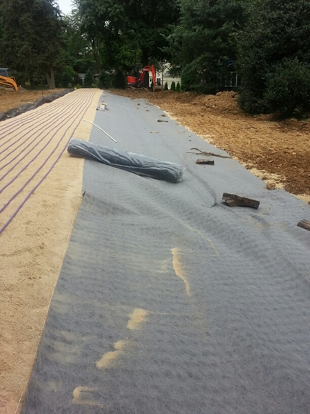
Cover With Geotextile Layer
Then the system is covered with a layer of geotextile synthetic fabric.
Covering The Mound
- 12” of suitable cover the top of the Micromound.
- 8” of suitable cover over the sides and shoulder of the Micromound.
- Cover the downsloping berm and extend the toe (the toe must support vegetation).

Final Grade
Surface water must move away from the Micromound and may not accumulate on top, or up slope, of the mound.
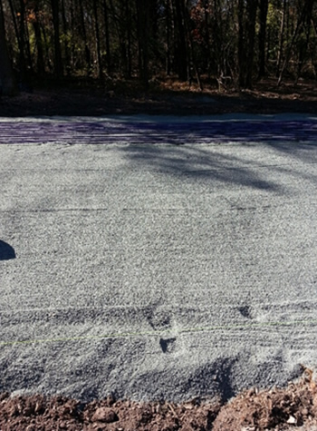
Vegetation
- Seed and straw the area immediately to avoid erosion.
- Sod is recommended.
- Establish and maintain aggressive turf.
- Erosion control may be necessary on some sites with steep slopes.
Winter Cover
Thick winter cover of straw or mulch is necessary for late fall installations.
Don’t Forget Tank Protection
Good fall protection will protect against harsh winter weather


Six Months After Installation